Last Updated: 14 Sep, 2026
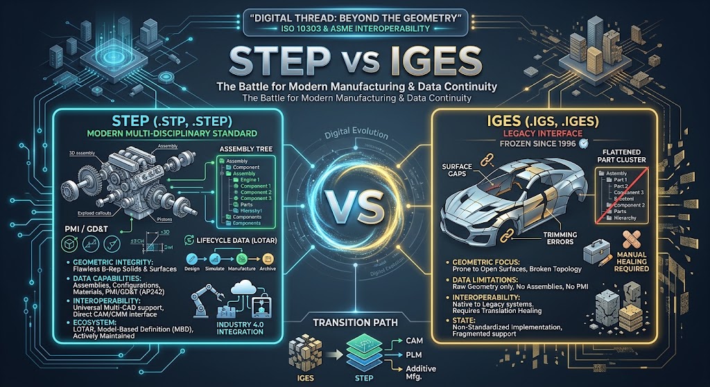
STEP vs IGES: Comparing Modern and Legacy CAD Exchange Formats
If you have ever received a 3D model from a client or vendor only to find broken surfaces, missing fillets, or a jumble of disconnected wireframes, you already understand the quiet frustration of CAD translation errors.
In product development and precision manufacturing, neutral file formats are the universal translators bridging the gap between proprietary modeling tools—such as SolidWorks, Autodesk Inventor, CATIA, Siemens NX, and PTC Creo. For decades, two formats have dominated neutral 3D exchanges: IGES (Initial Graphics Exchange Specification) and STEP (Standard for the Exchange of Product model data).
While both formats were designed to make CAD models vendor-independent, they belong to completely different technological eras. IGES represents the pioneering days of 1980s computer graphics, while STEP is the evolving backbone of modern digital manufacturing, Model-Based Definition (MBD), and Industry 4.0. Here is a practical, engineer-focused deep dive into how STEP and IGES work, how they compare head-to-head, and which format you should select for your next engineering or machining project.
1. What is IGES? The 1980s Pioneer
The Origins of IGES
Developed in 1979 through a joint effort by Boeing, General Electric, and the United States Air Force, IGES (Initial Graphics Exchange Specification, pronounced EYE-jiss) was officially published by the National Bureau of Standards (now NIST) in 1980. It was created to solve an urgent crisis: defense aerospace contractors were adopting incompatible computer-aided design systems, making digital collaboration across contractors nearly impossible.
IGES standardized how geometric elements—such as points, 2D lines, arcs, splines, and parametric surface patches (NURBS)—could be written into human-readable ASCII text files.
Why IGES Froze in Time
IGES solved crucial problems in the 1980s, but it was designed during an era when computer systems could barely handle surface modeling, let alone solid modeling or complex assembly hierarchies.
Key milestones of IGES:
- 1980: IGES Version 1.0 released (focused heavily on wireframes and basic drafting entities).
- 1990: IGES 5.0 introduced rudimentary B-Rep (Boundary Representation) capabilities, but widespread implementation across CAD vendors remained fragmented.
- 1996: Version 5.3 was released, representing the final official update.
In 1996, development on IGES officially ceased. The standard was retired and is no longer actively maintained. Today, when you open an IGES file (.igs or .iges), you are working with a data standard that has remained untouched for roughly three decades.
2. What is STEP? The Modern Engineering Backbone
The Evolution of ISO 10303
By the late 1980s, the international engineering community recognized that IGES had hit a dead end. Modern manufacturing needed more than just floating surface sheets—it required true volumetric solids, kinematic assemblies, dimensional tolerances, material callouts, and lifecycle management.
In 1994, the International Organization for Standardization (ISO) launched ISO 10303, colloquially known as STEP (Standard for the Exchange of Product Model Data).
Unlike IGES, STEP was architected from the ground up as a modular, extensible framework capable of describing a product across its entire lifecycle—from conceptual design to machining, inspection, maintenance, and recycling.
Common STEP Application Protocols (APs)
STEP files typically carry the extension .step or .stp. The standard is structured into specific Application Protocols (APs) tailored for distinct industrial workflows:
- STEP AP203 (Configuration Controlled 3D Designs of Mechanical Parts and Assemblies):
The baseline standard widely adopted in aerospace and mechanical engineering. It reliably stores boundary representation (B-Rep) solid geometry and basic assembly tree structures. - STEP AP214 (Core Data for Automotive Mechanical Design Processes):
An enhancement over AP203 popular in the automotive industry. It adds support for color assignments, layers, geometric tolerances, surface finishes, and wire harness data. - STEP AP242 (Managed Model-Based 3D Engineering):
The state-of-the-art modern standard, merging the best of AP203 and AP214 while integrating native support for Product and Manufacturing Information (PMI), 3D Geometric Dimensioning and Tolerancing (GD&T), semantic annotations, and tessellated mesh representations for additive manufacturing.
Unlike IGES, STEP is continuously updated by ISO committees to support digital twin workflows, cloud collaboration, and automated toolpath planning.
3. Head-to-Head Comparison: STEP vs. IGES
| Feature / Metric | STEP (.stp, .step) | IGES (.igs, .iges) |
|---|---|---|
| Standardizing Body | ISO (ISO 10303) | ANSI / US Air Force / NIST |
| Active Development | Active (Continually maintained) | Discontinued (Frozen since 1996) |
| Primary Geometry Model | True B-Rep Solids, Surfaces, & Curves | Primarily Surfaces, NURBS, & Wireframes |
| Topological Integrity | High (Watertight manifold volumes) | Low (Prone to open edges & sewing gaps) |
| Assembly Support | Full hierarchy, part mating, and instances | Weak/Flat ( अक्सर merges into disconnected parts) |
| Metadata & Colors | Supported (AP214/AP242: colors, layers, materials) | Minimal (Inconsistent color/layer support) |
| PMI & 3D GD&T | Fully supported in AP242 | Not supported |
| File Structure | Structured ASCII (EXPRESS schema) or XML | Fixed-column 80-character card image format |
| File Size Efficiency | Compact and efficient | Noticeably bloated text structure |
| Primary Use Case | CAD/CAM solid modeling, CNC, 3D printing | Legacy surface recovery, legacy wireframe tooling |
4. Key Technical Differences in Detail
1. Solid Geometry vs. “Hollow” Surface Quilts
The most critical practical distinction between STEP and IGES lies in how they define shape:
- STEP preserves topology: A STEP solid model knows which faces connect to which edges, forming a closed, watertight, manifold volumetric body. When you import a STEP file into CAD, your system immediately recognizes it as a solid with mass properties (volume, center of gravity, weight).
- IGES relies on independent geometry patches: Most IGES exports represent a model as a collection of loose trimmed surfaces, lines, and curves. When opened in modern CAD programs, these surfaces often import as non-manifold “surface quilts” with microscopic gaps at the boundary seams. Engineers must then spend valuable time running “knit” or “heal geometry” functions to stitch surfaces back into an airtight solid.
2. Assembly Structures and Hierarchies
If you are exporting a complex assembly containing hundreds of parts:
- STEP retains the assembly tree: Sub-assemblies, part naming conventions, coordinate systems, and component relationships remain organized.
- IGES flattens the file: IGES traditionally struggled with multi-body assemblies. In many translation pipelines, importing an IGES assembly collapses every component onto a single layer or drops component metadata entirely, turning an interactive assembly into an unmanageable cluster of unorganized surfaces.
3. File Size and Parsing Overhead
IGES files are formatted using rigid 80-column punch-card-style structures inherited from mainframe computing architectures. This rigid fixed-width text formatting adds substantial data overhead without providing extra engineering value.
STEP files use an expressive, structured data model written in the EXPRESS data modeling language (ISO 10303-11). For a part with equivalent geometric complexity, an IGES file is often 20% to 50% larger than a comparable STEP file, while conveying substantially less design intelligence.
4. PMI, GD&T, and Model-Based Definition (MBD)
As manufacturing shifts away from traditional 2D technical drawings toward Model-Based Definition, the CAD model itself must carry dimensions, datum features, and surface finish requirements directly in the 3D workspace.
- IGES cannot convey 3D GD&T: It only translates dumb geometry.
- STEP AP242 provides full semantic PMI support: Modern automated CMM inspection routines and 5-axis CNC programming suites can read geometric tolerances directly from a STEP AP242 file without manual operator interpretation.
5. When Should You Use IGES?
Given its limitations, does IGES still have a role in modern manufacturing? Yes, but only in targeted, niche scenarios:
- Legacy Systems and Heritage Projects: Aerospace, marine, and defense sectors frequently service machinery designed in the 1980s and 1990s. If an original file was generated in Computervision, CADAM, or an early CATIA version, IGES might be the only archival translation available.
- Surface-Only CNC Tooling: When exporting complex freeform styling surfaces (such as automotive body panels or cast tooling dies) strictly to generate surface finish milling passes, a clean NURBS IGES export can still suffice.
- Specialized Wireframe and Laser Scanning Output: Older optical coordinate measuring machines and legacy CMM software sometimes default to IGES for raw curve and point coordinates.
6. When Should You Use STEP?
For virtually every mainstream engineering, simulation, and manufacturing workflow, STEP is the unequivocal winner. You should use STEP for:
- Modern CNC Machining (CAM): CAM packages like Mastercam, Fusion 360, and hyperMILL require solid B-Rep topology to automatically recognize features like pockets, holes, chamfers, and tapers.
- Additive Manufacturing (3D Printing): STEP has increasingly replaced STL for precision additive workflows. STEP files eliminate the faceting and chordal deviation inherent in triangular STL meshes, allowing slicing software to generate mathematically pure arcs.
- Multi-CAD Engineering Collaboration: Whenever you share parametric mechanical designs between teams operating across different platforms (e.g., SolidWorks to NX), STEP ensures maximum fidelity.
- Long-Term Digital Archiving (LOTAR): ISO standards committees specifically curate STEP AP242 to ensure CAD data generated today remains readable and verifiable 50 years into the future.
7. Best Practices for Clean CAD Data Translation
To avoid messy translations regardless of the format you choose, keep these operational rules in mind:
- Default to STEP AP214 or AP242: If your CAD software asks which protocol to export, avoid default AP203 unless required by older legacy equipment. Choose AP214 for colors and layers, or AP242 for full MBD workflows.
- Verify Solid Continuity After Import: Always inspect the mass properties of the imported file. If the CAD software displays volume as zero or indicates surface bodies rather than solid bodies, execute an automatic healing/stitching pass before generating toolpaths.
- Set Tighter Modeling Tolerances Before Exporting: Translation gaps often emerge when the sender’s CAD system has a loose modeling tolerance (e.g., 0.01 mm) while the receiver’s software operates at 0.001 mm. Standardize your modeling tolerances across your supply chain.
- Purge Hidden and Construction Geometry: Suppress construction planes, unconsumed sketches, and sacrificial lofting surfaces before exporting neutral files. This minimizes file bloat and avoids confusing downstream CAM operators.
8. Summary: The Final Verdict
Comparing STEP and IGES is not a battle of equals—it is a generational transition.
- IGES is a retired legacy format that laid the ground rules for interoperability in the 20th century. While it remains useful for reading antique archives and isolated surface contours, its inability to reliably model volumetric solids and assemblies makes it obsolete for modern production.
- STEP is the living, breathing international standard for digital engineering. From watertight solid topology and assembly hierarchies to advanced 3D GD&T annotations, STEP is engineered to satisfy the rigorous demands of modern manufacturing.
Whenever you have the choice, export and share STEP files.
FAQ: Frequently Asked Questions
Q: Is a STEP file always higher quality than an IGES file?
A: Yes, STEP preserves full solid topology, volumetric mass, and assembly hierarchies, whereas IGES typically only transfers unstitched surface patches.
Q: Can 3D printers read STEP and IGES files directly?
A: Modern 3D slicers (like Bambu Studio and PrusaSlicer) directly import STEP files with smooth mathematical surfaces, but they generally do not support IGES.
Q: Why do IGES files frequently import as hollow surface quilts rather than solid parts?
A: IGES was designed before solid modeling was standardized, meaning it describes models as individual boundary surfaces without enforcing watertight closed-volume topology.
Q: Which STEP format should I choose: AP203, AP214, or AP242?
A: Select AP242 for the most modern standard with PMI and GD&T support, AP214 for basic parts needing colors and layers, and AP203 only for older legacy systems.
Q: Are STEP and IGES files editable like native parametric CAD files?
A: Neither format retains parametric feature trees (like sketches, extrudes, or mates), but both can be modified using direct modeling tools inside modern CAD software.
See Also
CAD File Formats at FileFormat.com
Open Source APIs for working with CAD file formats
File Format News – Your one stop for all the news related to file formats from around the world
File Format Forums – Post your queries in file format forums to get useful information from file format experts and community users
File Format Wiki –Explore file format categories for information about various file formats